Index
Home
About
Blog
From: John De Armond
Newsgroups: rec.outdoors.rv-travel
Subject: Re: dpdt installation
Date: Tue, 03 Apr 2001 02:07:15 -0400

best wrote:

> I'm installing an inverter into my slide in camper. I've never installed
> relay and don't know the correct terminology. It is a 120v 15amp double pole
> double throw, which I purchased from Radio Shack. It seems simple enough,
> but I
> need reassurance. I'm planning on joining the pairs for 30 amp capacity.

I suggest an alternative.  Get a 120 volt coiled, 30 amp defined
purpose contactor as is used in air conditioners.  The cost should
be under $15 from an AC parts or motor repair place.  The reason I
suggest this is that the contactor is vastly more rugged than the
Rat Shack relay.  Secondly, it is a bad idea to try and parallel
contacts if the relay will be opening under load.  Invariably one
contact opens first and the other one is left to break the 30 amps.

> 1]     I am planning to connect the coil [I like to think of it as the power
> sensor], to detect when shore or generator power is active so it disconnects
> the inverter from the 120 circuit.
> 2}     Alternatively, I could hook the coil into the Inverter AC out to
> disconnect the shore-generator power from the camper 120v circuit when I
> turn on the inverter from the remote switch.

I recommend connecting the coil to the inverter for several reasons:

1) assuming you'll be on shore power more than inverter power, the
life of the relay is extended by having it de-energized most of the
time.  Plus you don't have to worry about a relay buzzing all the
time you're on shore power.

2) The inverter must come up to voltage before the relay is picked
up.  This gives the inverter time to start and stabilize before
assuming any load.

Another suggestion is to include a second or two delay in the relay
circuit - easy to do with a delay-on-make module, available from the
same source for $12-15.  The reason for this is that for a few
seconds after power is dropped, induction motors generate.  If you
close the inverter in on this out of phase, which it invariably will
be, the inverter will experience a very high surge in current.  The
induction generation dies in a second or so.  This is ESPECIALLY
important if this inverter is sized to run your AC.

Before you make the final decision as to which side feeds the coil,
you must decide which power source you want to have priority.  If
you feed the coil from the inverter, it will have priority and will
take the load when turned on even if shore power is available.  If
you feed the coil from shore power, shore power will take the load
away from the inverter.  This might be desirable, in that if you
forget to turn the inverter off after you hook up to shore power,
the load will automatically be taken off the inverter.  This will
keep you from inadvertently either running your battery down or
heavily loading your converter.


> The following question shows my ignorance of the subject, but I need to
> know. Do I connect the hot or neutral to the "common" poles on the switch?
> According to the diagram on the dpdt, the common connectors are numbered 5
> and 6.

You really must switch both the hot and the neutral leads (which
rules out the rat shack relay).  The reason is, when you're on shore
power the neutral and ground should not be tied together.  When
you're on the inverter, the neutral and ground must NOT be tied
together.  The reason is that many inverters float the neutral above
DC ground.  If the neutral is grounded, the inverter will shut down
if you're lucky.  If not, it will burn out.  I can guarantee that
the Vector inverter works this way, as I currently have one on my
bench reverse engineering it.

John
From: John De Armond
Newsgroups: rec.outdoors.rv-travel
Subject: Re: Question.....120 volt fridge
Date: Sun, 15 Jul 2007 02:08:46 -0400
Message-ID: <t9dj93dk8hq0io578auuj0b4d3vee0qvm0@4ax.com>
If I follow that somewhat convoluted description (must be yankee-ese...), you want
your 120 VAC refrigerator to automatically transfer back and forth from shore to
inverter power.
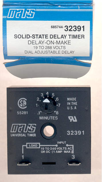
What is required is two DPDT relays with suitably rated contacts for the refrigerator
load and 120 VAC coils. You'll also need a time delay relay such as this:
One relay has its normally closed contacts connected between shore power and the
refrigerator.  The second relay has its normally open contacts connected between the
inverter and the refrigerator.  The first relay's coil is connected to the inverter
power directly.  The second relay is connected to shore power through the time delay
relay to the inverter.

It works as follows.  When shore power is available and the inverter is off, both
relays are de-energized.  Power flows through relay 1's NC contacts to the reefer.

When the inverter is turned on, #1 relay energized immediately, isolating the reefer
from the shore power line.  After the time delay expires, #2 relay energizes,
connecting the inverter to the reefer.

One might ask, why all the relays and time delay?  Why not use one DPDT relay to
switch between shore and inverter power?  Easy.  Inverter blue smoke is valuable and
must not be released.

An induction motor such as that in the compressor is an equally good generator.  If
the compressor is running and the power is switched instantly from shore power to the
inverter, the motor now acting as a generator will feed back out-of-phase power to
the inverter.  Blue smoke leaks out.  The inverter and shore power are out of phase
because the inverter free runs.  It is probably even a slightly different frequency.

I leaked blue smoke from an inverter learning this lesson.  What my system does is
stop the compressor by opening the shore power connection.  It then waits the time
delay interval for the compressor to stop (and optionally, several minutes to recycle
the compressor).  Then inverter power is applied and the compressor starts normally.
No delay is necessary going the other way, as shore power doesn't leak blue smoke.

To protect the compressor from short cycling, set the time delay to 3 minutes or
more.  This is particularly important with an inverter, as the compressor's heavy
locked rotor current draw might trip the inverter when otherwise the inverter could
handle the load.

The current involved is small so any small relay rated for the voltage and current
can be used.  Rat Shack probably has 'em.  If not, HVAC fan relays can be used, as
can "crystal can" octal base plug-in relays.  The time delay relay is a standard HVAC
item that can be gotten from a local appliance parts warehouse, Graingers, etc.

There should be room in the back of the fridge to mount the relays.  That's where I
put mine.

This circuit is "inverter priority", that is, the inverter powers the fridge
regardless of whether there is shore power.  "Shore power priority" would involve a
slightly more complicated circuit.  I can describe it if you want that style.  If you
need me to, I can sketch this circuit and post it to my website.

John


On Sat, 14 Jul 2007 10:41:26 -0400, "JerryD\(upstateNY\)" <jerryd@wherever.com>
wrote:

>I've got another question.
>I want to attach an electric supply from the inverter AND shore power to the
>fridge.
>When I shut off the MH and hook up to shore power, the electric will follow
>back to the inverter but won't go anywhere because the selonoid connection
>will be broken.
>I understand I would have to hook the positives and neutrals to the correct
>terminals.
>Will this damage the inverter ?
>The reason I want to do this is that it will be one more thing I won't have
>to worry about changing when we stop for the night or when we are leaving.
>
>
>
>JerryD(upstateNY)
>
From: John De Armond
Newsgroups: rec.outdoors.rv-travel
Subject: Re: Is there a 2-way 'manual' switch to go between inverter and shore
	power for the TV ?
Date: Sat, 16 Feb 2008 00:41:47 -0500
Message-ID: <rjscr31jnsuv35j618p2c49t5kpv9vguq7@4ax.com>

On Fri, 15 Feb 2008 21:40:47 GMT, ratatouillerat@yahoo.com wrote:

>It occurs to me that if you can't even find such a switch, you will
>likely not be able to install it so it works and works safely.  If you
>really want such a switch, I suggest you consult an electrical
>technican to find it and wire it.

Actually there is.  It's called a double pole, double throw, center off, center
hesitate toggle switch.  The hesitate function prevents the switch from going
straight through off which will damage the inverter if motors are still turning.  One
has to release the pressure on the toggle a bit before it will flip to the other
throw.  This kind of switch is commonly used as a reversing switch on small AC
motors.

>
>Actually, rather than a manual switch, I would suggest one that senses
>when shore power is available and switches to that.

This sounds simple but in practice it lets the blue smoke out of the inverter as
often as not.  I had just such an automatic system set up in my rig.  If shore power
was available and I turned the inverter on, the transfer relay would snap and the
fault light on the inverter would come on, never to go out again.

Fortunately I could replace the transistors in the inverter.  It happened again.  I
thought it might be the inverter (1kW Vector) so I changed to a POB 1kW.  Same thing.
In all cases, only one polarity of transistors were blown, which gave me a clue.

After instrumenting my rig, what I found was that the switch from shore to inverter
power happened so fast that the inverter came online while the various motors around
the rig were still turning (AC's fan, etc)  The motor acts as an induction generator
for awhile until its store energy is dissipated.  The inverter almost invariably
comes up out of phase and so a huge fault current flows for about a half cycle. Close
to 50 amps in the most pathological instances.

Another secondary problem that I identified was with switch-mode power supplies like
are in modern converters, TVs, computers and other stuff.  They all contain inrush
limiting thermistors that limit how much current can flow at the instant of
energization when the input filter capacitors are empty and thus present practically
a dead short.  Problem is, they need to cool for a few seconds before they can do
their thing again.  Not nearly enough time during the fraction-of-a-cycle it takes
for the relay to trip.

If an automatic changeover is really desired then one could use two relays with a
time delay between them. I thought about it for a bit and decided that it was getting
way too complicated, especially since I'd have to flip the inverter switch anyway.

My solution was a 30 amp 3 pole version of the switch I described above.  The third
pole switches the 12 volt control voltage to the inverter.

In use, I flip the switch from shore power to center-off.  This kills power to the
rig.  The mandatory hesitation reminds one to take a little extra time.  It also
prevents one from bumping the switch directly from shore to inverter power.  After a
couple of seconds I flip the switch to inverter.  Two of the poles connect hot and
neutral from the inverter to the rig while the third pole energizes the inverter.

Smooooooth as silk!

John
Index
Home
About
Blog